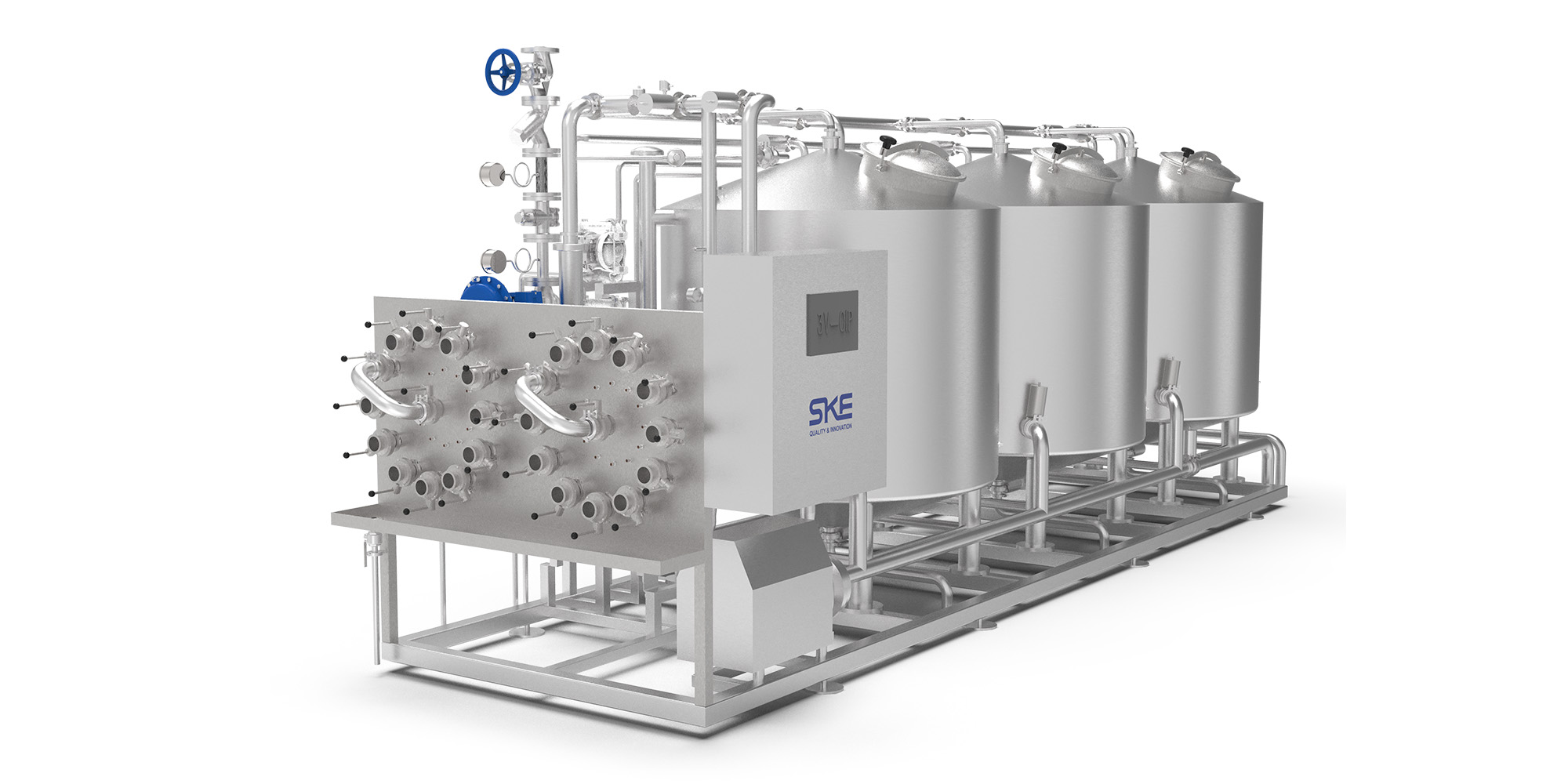
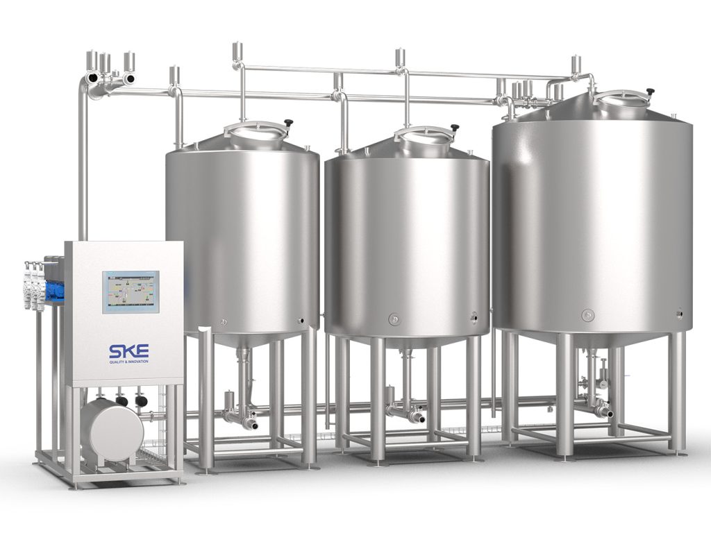
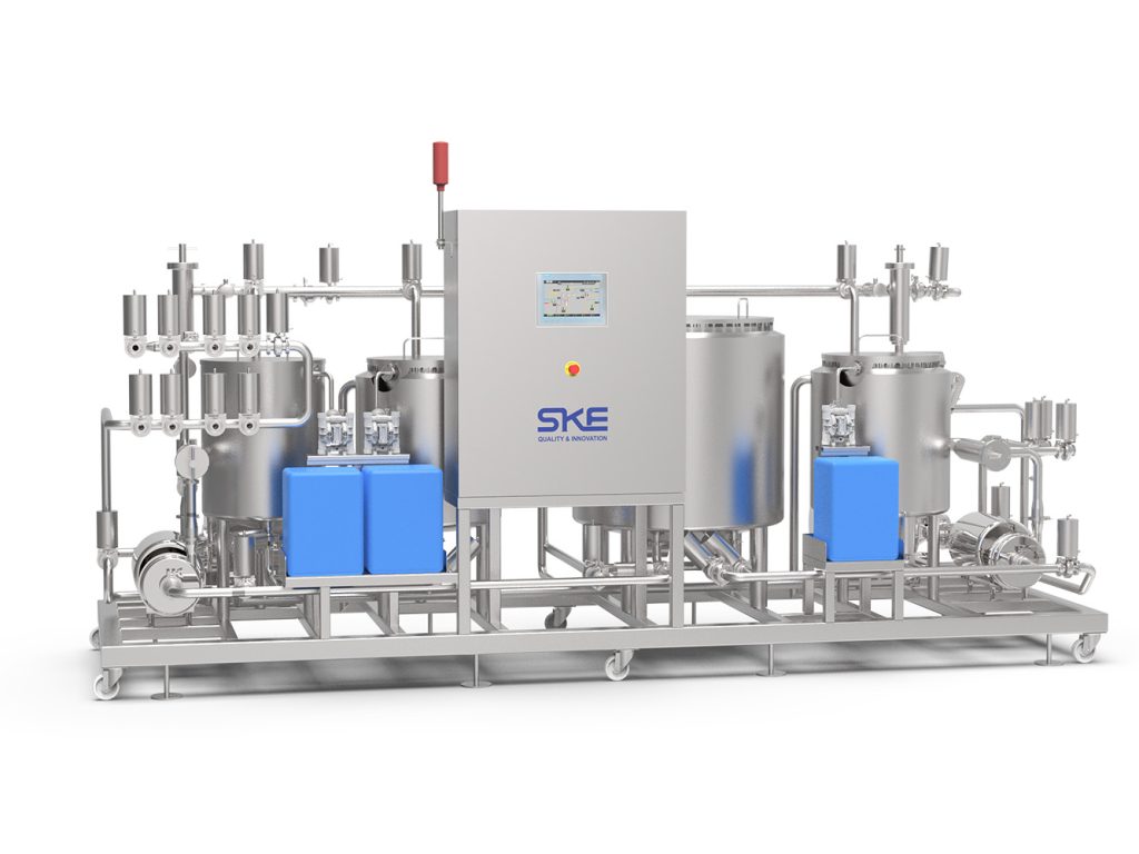
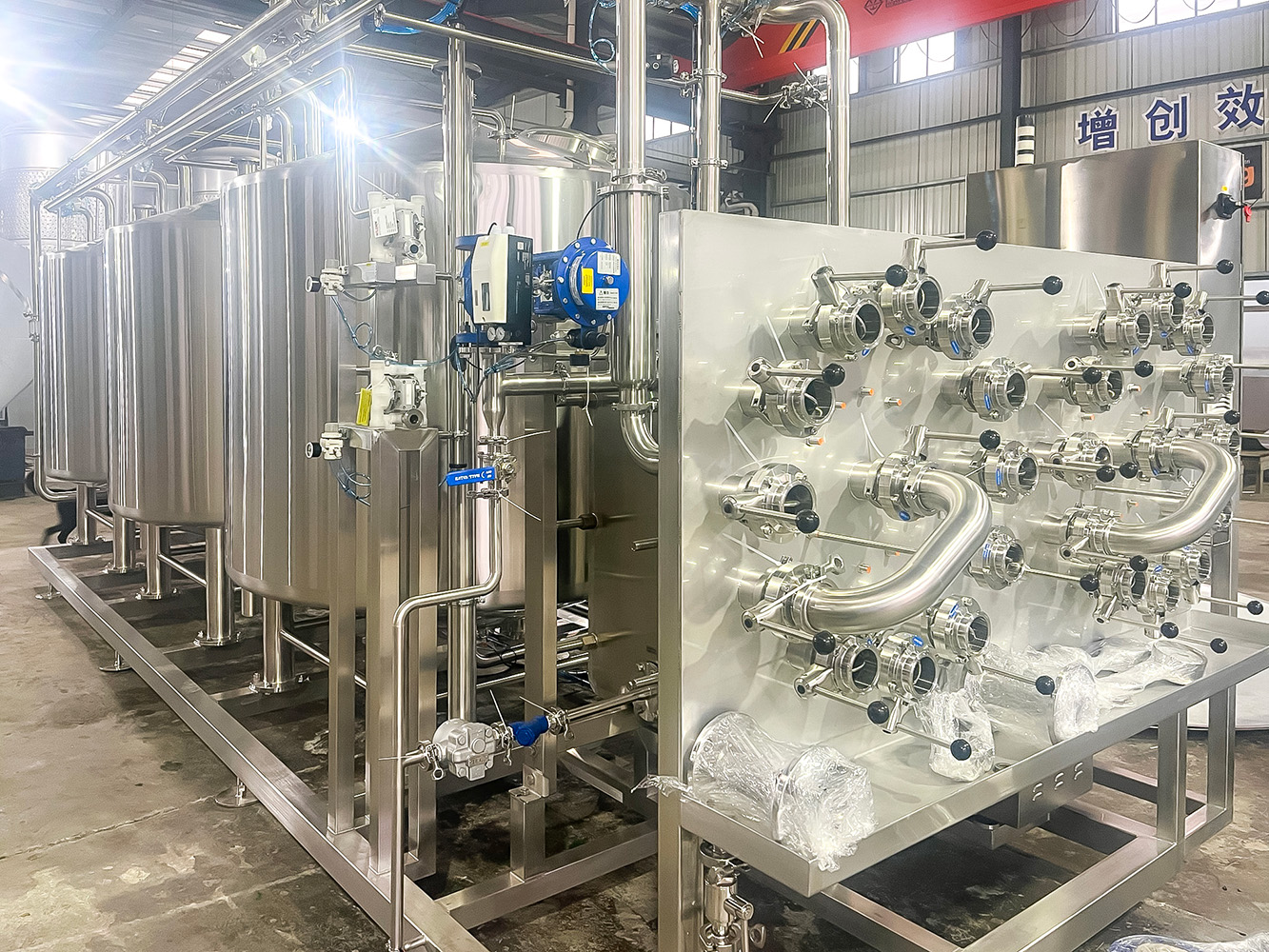
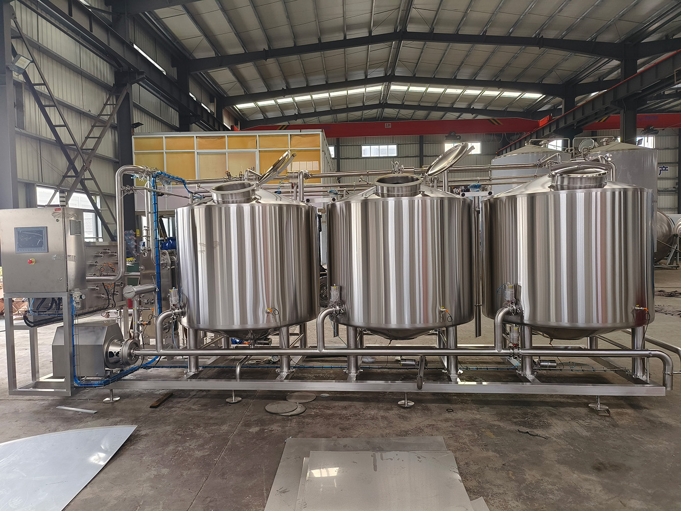
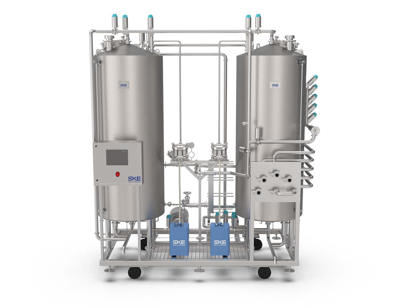
SKE Equipment

cip brewing

Automated CIP Brewery System

CIP ( cleaning in place) system is a very efficiency cleaning system which is widely used in diary, beer, beverage, medicine industries.

CIP System

CIP ( cleaning in place) system is a very efficiency cleaning system which is widely used in diary, beer, beverage, medicine industries.

SKE CIP system has below parameters,

  • Simple operation, working security, high efficiency
  • Multi CIP supply and return
  • Deeply cleaning and sterilization for better quality product
  • Compact design for space saving
  • Saving energy and water
  • Fully automation for labor saving and non- operation error

Project Scope

CIP System will be completed with the following equipment, instrumentation and control panel plus other item SKE feels necessary for a properly functioning CIP Skid. The CIP tanks amount can be designed as customer’s CIP process, each consisting of the following:

  • One (1) Fresh Rinse Tank
  • One (1) CIP Recovery Tank
  • One (1) Acid/Flex Tank
  • One (1) Caustic Tank
  • One (1) Sterilizer Tank

– Two 2” Tank discharge valve manifold

  • Automatic Butterfly Valves With ThinkTop
  • Manual Butterfly valve for low point drain; manual drain of tanks

-Two 2” Return valve manifold (return to tanks or to drain)

  • Automatic Butterfly Valves With ThinkTop

-Chemical dosing pumps for sodium hydroxide (Caustic) and Nitric Acid Blend (Acid/Flex)

-Plastic chemical tanks and chemical piping

-Centrifugal CIP Supply Pumps

-Centrifugal CIP Mixing Pumps

-Centrifugal CIP Return Pumps

-Two Sets of Heating Package complete with steam control valves and ancillary equipment

  • Alfa Laval Plate heat exchangers
  • Spiraxsarco steam valves

-Instrumentation

  • RTD Supply Temperature Out
  • RTD Return Temperature
  • Pressure Sensor
  • VFD for Supply Pump (Mounted in Customer Offered Control Cabinet)
  • Flow Sensor
  • Conductivity Sensors
  • Liquid level sensors

-Piping & Fitting

  • Pump Suction Line “Y” Strainer or “Tee” Strainer. Strainer must be accessible for each removal and manual cleaning.

-Plateform & Ladder

Construction

The system will be made by 304SS Rectangular Tube Main Frame (#4 Finish, milled), adjustable feet for leveling.

Materials of Construction – Sanitary Piping

  • 316SS tubing and fitting, polished ID/OD
  • Tri-Clamp Type Fittings

Materials of Construction – Supports

  • Hanging material to be 304SS 1 ½” Schedule 40, polished OD
  • 304SS RG Hex hangers with PVC inserts
  • Hangar support to be ¾” round bar

Materials of Construction and Features– Tanks

  • 304/316 SS
  • Inner shell thickness 2mm; Outer shell thickness 2mm
  • Drains – Manual Butterfly
  • Chemical dosage inlet in detergent and acid tank
  • CIP Return Inlet with dip tube
  • 2B Internal finishes, #4 external finishes
  • All welds ground and polished in direction of welds

Automatation Package

The following items to be included with the automation package.

  1. Control enclosure hardware such as a PLC, HMI terminal, I/O, power supplies, power handling equipment, VFDs, control enclosure, and other related control hardware
  2. PLC and HMI programming to support the CIP Skid including options for manual override

Controls programming (PLC and HMI) for the CIP Skid to perform routing of the CIP solutions. The system is based on a configurable design allowing for a customized cleaning process to be setup by the operator. Configuration screen will allow an operator to specifically setup a cleaning sequence based on tank to be cleaned, time, temperature, and concentration of solution.

Programming of the automatic and manual operating capabilities into the CIP System is included. The automatic system will be controlled via designated CIP circuits to be selected by system operators with system safety interlocks. The manual operation of the system will allow for singular valve pulsing, direct pump control with ON/OFF and speed modifications capabilities.

Voltage – Customize

Ce certification

CIP Return Line Flow Switch connected within CIP return pump suction side. Flow switch can be IFM – SI6800 with 2” tri-clamp adapter including cables.

Update cookies preferences
en_USEnglish